
- All
- Product Name
- Product Keyword
- Product Model
- Product Summary
- Product Description
- Multi Field Search
Please Choose Your Language

Views: 0 Author: Site Editor Publish Time: 2026-07-23 Origin: Site


A reliable electrical connection relies on physics, not guesswork. A proper crimp creates a gas-tight cold weld. A poor one results in voltage drop, heat buildup, or catastrophic failure. Every time you connect a bare wire, you depend on precise mechanical force.
Many technicians and engineers experience wire pullouts daily. You might use the wrong tool profile for a specific terminal. Sometimes, operators rely on inconsistent manual pressure rather than calibrated mechanics. These simple errors compromise system integrity across robotics, automotive wiring, and complex HVAC networks. Loose connections create hidden resistance. They ultimately lead to unpredictable faults over time.
We will break down the internal mechanics of a non insulated terminal crimper. You will understand exactly why specific die profiles matter for secure connections. Finally, we will outline strict evaluation criteria. You will learn how to select tools guaranteeing repeatable, compliance-standard outcomes.
Non-insulated crimpers use a specific "indent" or "W-shaped" die to fold and compress the terminal barrel directly into the wire strands, creating a solid mass.
Unlike tools for insulated connectors, non-insulated dies are designed to pierce and deform bare metal without damaging an outer plastic sleeve.
Upgrading to ratchet crimping pliers eliminates human error by preventing the jaws from opening until the optimal crimp depth is achieved.
Verifying a successful crimp requires matching the terminal, wire gauge (e.g., using a 20-10 AWG crimper), and conducting standardized pull-tests.
You must understand the physical transformation during a successful crimp. You are not just squashing a metal tube flat. You are essentially forging two separate pieces of metal into one solid block. A well-designed non insulated terminal crimping tool applies targeted pressure to completely remove oxygen from the connection point. We call this outcome a gas-tight cold weld. Air gaps invite moisture. Moisture causes oxidation. Oxidation drastically increases electrical resistance.
The die profile does most of the heavy lifting. You will primarily see two shapes for bare metal terminals. The first is a single indent profile. It drives a sharp point downward into the metal barrel. The second is an F-crimp or W-crimp design. The punch presses the terminal seam downward. It forces the wire strands to fold, deform, and compress tightly into a single cross-section.
F-Crimp (Open Barrel): Folds the metal tabs back onto themselves. It digs deep into the wire strands.
Indent Crimp (Closed Barrel): Pierces the center of the metal cylinder. It locks the copper strands in place.
High-quality tools utilize an intelligent leverage system. Mechanical advantage is crucial here. A long handle combined with specialized pivot points multiplies your hand force. You achieve the exact tonnage required to fuse copper and brass perfectly. A direct-action pliers simply cannot match this concentrated force.
Using generic pliers leaves visible air gaps inside the terminal barrel. Improperly calibrated tools produce the same dangerous result. You risk immediate oxidation. High electrical resistance eventually generates enough heat to melt surrounding components. A dedicated indenting or folding die prevents these catastrophic failures entirely.
You must evaluate different crimping solutions before outfitting your toolbox. Comparing the two main tool categories guides your shortlisting logic. The most common mistake involves using one generic tool for every terminal type. You cannot treat bare metal and plastic-sleeved connectors the same way.
Die shape differences dictate the appropriate application. Insulated dies feature oval or color-coded nests. They squeeze the terminal gently. Their smooth surfaces avoid puncturing the PVC or nylon insulation. Non-insulated dies feature sharp, defined anvils. Engineers design them to aggressively bite into bare metal. They fold thick brass or copper without tearing through plastic, because there is no plastic present.
Tool Type | Die Profile | Primary Action | Target Material |
|---|---|---|---|
Insulated Crimper | Smooth, oval, double-crimp | Gentle compression | PVC/Nylon sleeved terminals |
Non-Insulated Crimper | Sharp indent or W-shape | Aggressive piercing/folding | Bare brass, copper, steel terminals |
The cross-contamination risk in the field is severe. You might grab an insulated terminal crimper to secure a bare metal ring terminal. The smooth oval die simply flattens the bare metal. It under-crimps the connection badly. The wire easily slides out under minimal tension. Conversely, using a non-insulated tool on a nylon terminal shreds the protective sleeve. The sharp indent tears right through the plastic insulation. It exposes live electrical wires and ruins the protective barrier.
Always keep these tools visually separated. Best practices suggest color-coding tool handles. This reduces confusion during fast-paced assembly tasks. You protect the integrity of the terminal and the safety of the entire electrical circuit.
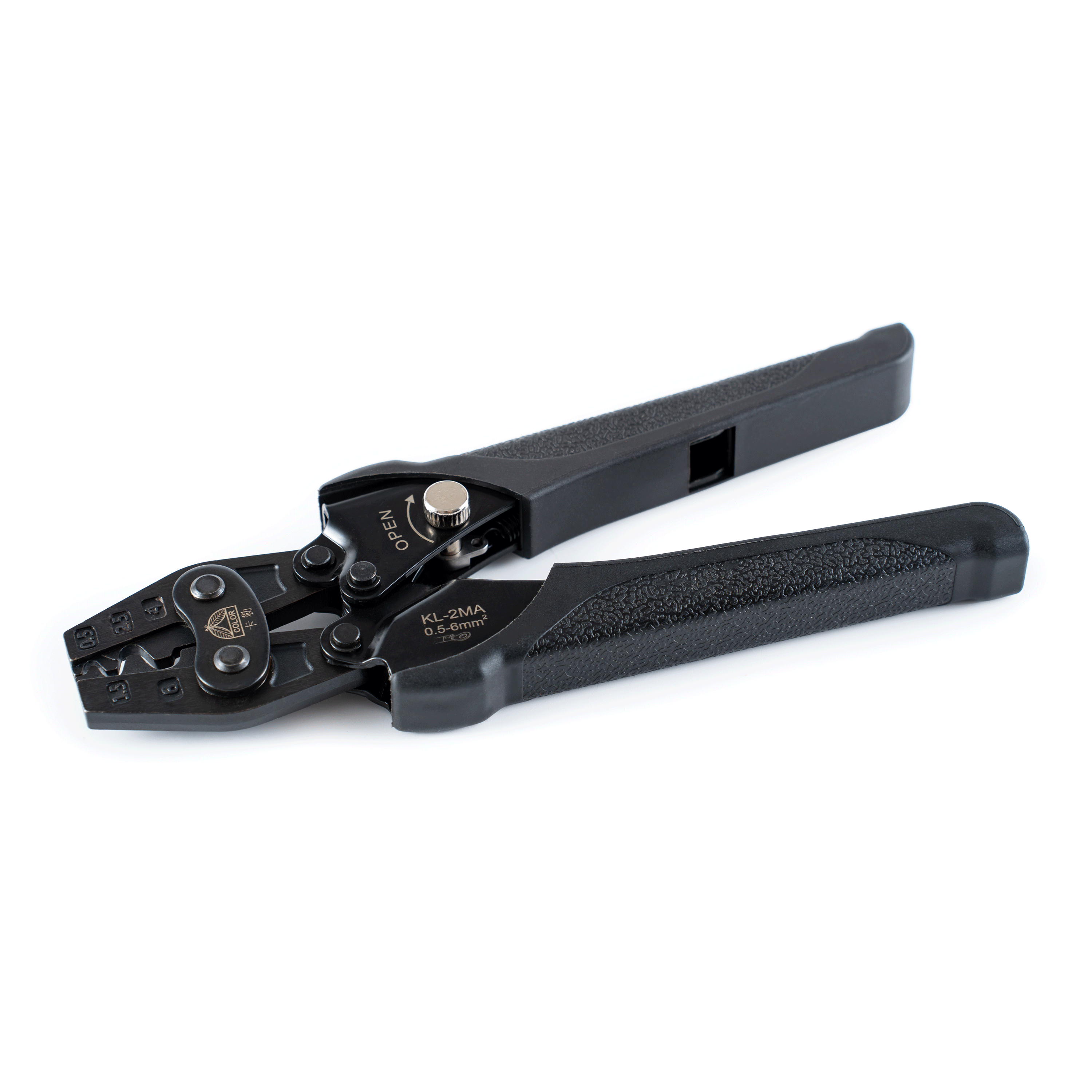
Manual "squeeze-until-it-feels-tight" tools present a massive business problem. They lack scalability. They destroy consistency across a team of technicians. One person might grip the tool like a vise. Another person might release the handles too early. This variance guarantees inconsistent electrical connections.
The built-in ratchet acts as a forced-quality gate. Upgrading to ratchet crimping pliers solves this inconsistency permanently. You insert the terminal and wire. You begin squeezing the handles. The internal gears lock into place. The cycle must be fully completed before the tool releases its grip. The jaws will not open until they achieve the precise factory-set crimp depth. This simple mechanism completely prevents under-crimping.
Professional-grade tools feature adjustable tensioning systems. Over thousands of cycles, metal dies slowly wear down. The crimp depth changes minutely. You can compensate for this wear using the star wheel.
Locate the locking screw near the star wheel on the tool body.
Remove the screw carefully to free the adjustment dial.
Rotate the wheel toward the positive (+) symbol to increase compressive force.
Replace the locking screw to secure the new tension setting.
We must also frame the ergonomic return on investment. High-volume environments demand repetitive hand movements. Panel builders and wiring harness assemblers suffer from rapid hand fatigue. A well-designed ratcheting system spreads the force over the entire handle stroke. It automatically holds the terminal in place before the final squeeze. This reduction in hand strain boosts overall productivity. It significantly lowers the risk of repetitive motion injuries.
You must match your tool's capacity to your project scope. Scalability and compatibility depend on correct sizing. A single tool rarely covers every conceivable wire diameter. You need dedicated instruments for specific ranges.
Consider the jaw nests on a standard 20-10 AWG crimper. The tool head features multiple distinct semi-circles. Engineers call these nests. A typical layout includes three separate slots: 20-18 AWG, 16-14 AWG, and 12-10 AWG. You must insert the terminal into the exact corresponding nest. Placing a 10 AWG terminal into a 16 AWG nest crushes the metal completely. Placing a 20 AWG terminal into a 10 AWG nest applies zero pressure. Using the wrong nest destroys the tensile strength of your connection.
We must clarify assumptions regarding wire types. These crimpers are explicitly engineered for stranded wire. Stranded copper deforms easily. The individual strands shift and fill the empty voids inside the terminal barrel. Attempting to crimp solid core wire rarely works. Solid wire does not compress well. It resists the die shape. You often end up with a loose connection or damaged tool jaws. Always use stranded wire for these applications.
Buyers need strict evaluation criteria when selecting tools. Always look for laser-etched markings directly on the steel dies. High-quality manufacturers etch both AWG and DIN millimeter sizes clearly. Painted markings wear off quickly. Laser etching remains visible forever. Clear markings allow quick identification. They heavily reduce human error in dimly lit field environments.
AWG Range | Metric Equivalent (mm²) | Common Terminal Indicator | Typical Application |
|---|---|---|---|
20 - 18 AWG | 0.5 - 1.0 mm² | Often Red (if insulated, but applies to bare sizing) | Sensors, small LED arrays |
16 - 14 AWG | 1.5 - 2.5 mm² | Often Blue | Standard automotive, robotics |
12 - 10 AWG | 4.0 - 6.0 mm² | Often Yellow | HVAC power lines, heavy motors |
You must move beyond tool features and demonstrate trustworthiness through validation. An electrical connection is only secure if it passes industry-standard checks. Quality control separates amateur work from professional engineering.
Visual inspection is your first line of defense. A passing non-insulated crimp looks highly specific. First, check for a "bell mouth" on the wire-entry side of the terminal. The metal edge should flare outward slightly. This flare prevents the sharp barrel edge from cutting into the copper strands during vibration. Second, ensure zero stray strands sit outside the barrel. Every single copper wire must be captured inside the crimp. Finally, check the wire protrusion. The stripped wire should extend just past the front edge of the terminal barrel. It should not protrude far enough to interfere with the mating connector.
The pull test measures raw tensile strength. Industry bodies like UL define strict standard quality control checks. A properly crimped 10 AWG wire should withstand up to 80 pounds of mechanical pull force before separating. A 16 AWG wire typically needs to hold at least 30 pounds. If you apply a calibrated weight and the wire slips out, the crimp has failed.
You need a framework for troubleshooting failures. If a crimp fails a pull test, you must diagnose the root cause immediately.
Undersized wire: Did you put an 18 AWG wire into a terminal built for 14 AWG?
Oversized terminal: Did you select the correct nest size on your dies?
Poor calibration: Has the tool worn down? Does the star wheel require tightening?
Improper stripping: Did you strip too little insulation, causing the die to crimp over plastic instead of bare copper?
Systematically checking these variables ensures long-term reliability. Good tools provide consistent force, but the operator must control the setup variables.
We must reiterate one absolute fact. A non-insulated terminal crimping tool is a precision instrument. It is not a generic pair of pliers. The correct indent die profile creates a true cold weld. The integrated ratchet mechanism functions as a non-negotiable quality gate. Together, they guarantee electrical safety and mechanical reliability.
Use clear shortlisting logic before buying. Evaluate your daily volume needs first. High volumes absolutely require ratcheting mechanisms to prevent fatigue. Check your required wire gauge range thoroughly. Ensure the tool covers the exact AWG sizes you use most frequently. Finally, verify required certification standards. Tools capable of meeting UL or CE pull-test standards justify their place on your workbench.
Take action immediately. Audit your current crimping tools for excessive jaw wear. Verify your die profiles perfectly match your terminal types. Invest in calibrated ratchet tools for all critical applications. Secure connections prevent future failures.
A: No. Pliers flatten the terminal rather than folding it into the wire strands. This fails to create a cold weld. It leaves air gaps that cause corrosion, high resistance, and potential fire hazards. A hammer crushes the metal randomly and destroys the mechanical integrity of the connection entirely.
A: A properly executed crimp with the correct tool is gas-tight. It is mechanically superior to soldering in high-vibration environments. Soldering after crimping can actually create a brittle stress point. The wire becomes stiff where the solder wicks up, making it highly likely to snap under movement.
A: Wire pullout usually results from three main errors. You might strip too much or too little wire insulation. You might use a die nest that is too large for the specific AWG size. Finally, you might use a non-ratcheting tool that simply didn't apply enough compressive force.


