
- All
- Product Name
- Product Keyword
- Product Model
- Product Summary
- Product Description
- Multi Field Search
Please Choose Your Language

Views: 0 Author: Site Editor Publish Time: 2026-07-20 Origin: Site


A poor electrical crimp acts as a hidden point of failure in any system. It frequently leads to sudden voltage drops, dangerous arc faults, or wires pulling loose inside critical panels. When a wire pulls loose, it exposes live current. This creates immediate fire hazards. You cannot afford such risks in residential or commercial wiring setups. You might not notice the flaw immediately, but the damage quietly escalates over time. An insulated terminal crimping tool solves this precise issue.
We define this as a specialized hand device designed to mechanically compress pre-insulated connectors—like ring, spade, or butt splices—onto stranded electrical wire. Crucially, it secures the metal core without breaching the delicate protective plastic sleeve. Many generic tools claim they can handle wire termination tasks. However, relying on a purpose-built instrument remains non-negotiable. You need it to guarantee safety, strict electrical compliance, and connection longevity. Technicians in HVAC, automotive repair, and industrial maintenance rely on proper tools to avoid catastrophic equipment failures. In this comprehensive guide, you will learn how to identify, select, and utilize the correct instrument for flawless wire termination.
Application Specificity: Insulated terminal crimpers use distinct oval or double-crimp jaw profiles to prevent puncturing nylon or PVC insulation.
Mechanism Matters: A ratchet wire crimper guarantees a full-cycle compression, removing human error and grip-strength variability from the equation.
Sizing Standards: Most tools are calibrated for standard color-coded ranges (e.g., Red/Blue/Yellow), with specialized dies available for precise ranges like a dedicated 20-14 AWG crimper.
Quality Assurance: A verifiable, compliant crimp requires matching the terminal type, wire gauge, and tool die precisely.
Connectors rely heavily on an external plastic sleeve for protection. Usually, manufacturers mold them from durable nylon or vinyl. These synthetic materials require a specific, gentle compression approach. You cannot simply crush them flat. They demand a wider, smoother profile to flow correctly around the internal metal barrel. A properly formed connection literally fuses the wire strands together. The copper strands deform and compress into a solid mass. The surrounding plastic sleeve must stretch without tearing. If you use improper dies, the plastic fractures. Once the plastic fractures, moisture inevitably creeps inside. Oxidation occurs rapidly. Oxidation raises electrical resistance, which ultimately generates dangerous heat.
Jaw profiles dictate your success. We must contrast the asymmetrical jaws of a dedicated insulated terminal crimper against standard bare wire designs. Uninsulated bare terminals require sharp, piercing "W" indent dies. They push deeply into the metal to create a cold weld. If you apply a "W" die to nylon, it slices right through the jacket. It exposes live wire and destroys dielectric integrity. Insulated dies typically feature a rounded oval or double-crimp shape. They cradle the plastic while squeezing the internal metal barrel securely.
Insulated terminals also strictly require stranded copper wire. Solid core wire does not compress properly inside these barrels. When you squeeze the handles, the tool forces the individual strands to reshape. They fill every microscopic void inside the metal tube. This structural deformation creates a gas-tight seal. A gas-tight seal stops ambient oxygen from corroding the copper over decades of continuous use.
Many casual users buy generic multi-tool kits. They often contain cheap terminal crimping pliers. These flat, stamped-steel devices lack mechanical precision. They present a major electrical hazard in professional settings. You risk severe under-crimping during installation. The wire simply pulls out under minimal physical tension. Alternatively, users squeeze too hard and cause severe over-crimping. This fractures the plastic casing. It introduces airborne moisture and drastically increases internal electrical resistance.
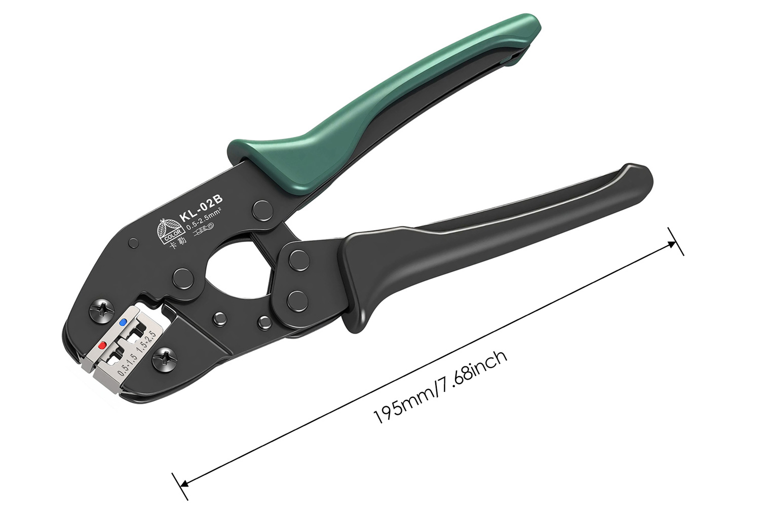
Choosing the right mechanism dictates long-term system reliability. We generally classify crimpers into two distinct operational groups. You must understand their mechanical differences before upgrading your toolkit.
Non-ratcheting plier models offer some minor baseline benefits. They remain incredibly lightweight in a tool pouch. You might keep them around for sudden emergencies. They work adequately for highly infrequent, low-stakes DIY fixes. However, they rely entirely on operator grip strength. You cannot guarantee consistent compression force. This variability ruins uniformity across multiple panel connections. Hand fatigue sets in quickly. Your tenth crimp will likely be much weaker than your first.
Conversely, industry professionals depend heavily on locking mechanisms. A ratchet wire crimper locks automatically during the downward stroke. It refuses to release early. You must fully close the metal jaws to reach a factory-calibrated depth. This design physically prevents partial crimps. It entirely removes human error from the equation. You gain complete confidence in every single connection.
Ratcheting designs deliver massive compliance value. They ensure standardized pressure on every single terminal block. Installers avoid severe hand fatigue during high-volume daily jobs. Furthermore, using these devices meets strict electrical code standards. Inspectors expect mechanically verifiable, uniform connections across all installations.
Feature | Standard Pliers (Stamped Steel) | Ratchet Wire Crimper |
|---|---|---|
Mechanism | Manual hinge, no automatic locking system | Internal toothed gear, full-cycle secure lock |
Pressure Control | Relies entirely on operator grip strength | Factory-calibrated mechanical depth |
Consistency | Highly variable, prone to failure | 100% repeatable across thousands of uses |
Primary Use Case | Emergency vehicle kits, rare DIY tasks | Professional HVAC, auto, and industrial wiring |
You must evaluate tools using strict mechanical benchmarks before purchasing. We outline the most crucial specifications below. Follow these rules to avoid acquiring substandard equipment.
Wire Gauge (AWG) Compatibility: Standard models usually cover the 22-10 AWG range. They utilize a universal color-coding system. Red covers 22-18 AWG. Blue covers 16-14 AWG. Yellow handles 12-10 AWG. Sometimes, technicians focus strictly on smaller control wiring. In those cases, sourcing a dedicated 20-14 AWG crimper makes perfect sense. It provides tighter mechanical tolerances for delicate sensor lines.
Die Quality and Alignment: Always inspect the metal jaws carefully. Look for investment-cast or precision-machined dies. Cheaply stamped dies often misalign under heavy pressure. Misaligned jaws create uneven force, leading to highly asymmetric, weak connections. Precision-machined dies undergo rigorous heat treatment. They resist wear over thousands of cycles. Stamped dies bend slightly during every single use.
Adjustable Tension (Star Wheel): Professional tools feature a tension adjustment star wheel. Internal metal springs naturally lose resistance over time. You must tighten this calibration wheel periodically. It maintains the manufacturer-specified crimp height as the equipment ages. Without this wheel, the tool loses its reliability after a year of heavy use.
Quick-Release Trigger: Never buy a ratcheting model lacking an emergency release lever. Sometimes, a terminal seats incorrectly halfway through a compression cycle. The quick-release lets you abort the operation safely. It prevents costly damage to both the tool jaws and the wire itself.
Executing a perfect termination requires strict visual validation. Leading connector manufacturers like TE Connectivity and Nichifu publish rigorous technical guidelines. You must inspect your manual work against these established industry standards.
Here is what a successful, fully compliant implementation looks like:
Symmetrical compression exists across the entire metal barrel.
Wire strands remain slightly visible protruding at the terminal end.
Outer plastic insulation stays completely intact without any stress cracks.
The connection effortlessly survives a manual pull-test retention check.
The wire jacket enters the insulation grip properly for robust strain relief.
Conversely, you must reject defective connections immediately. Common failure indicators include:
Pierced or severely torn plastic insulation (usually indicating the wrong die size).
Extruded metal "dog ears" bulging from the sides (caused by severe over-crimping).
Loose or completely missed wire strands (indicating under-crimping or poor wire stripping).
Microscopic stress lines in the vinyl turning white under bright light.
Visual checks only go so far. We highly recommend performing destructive pull-tests. Take the first few connections from a new production batch. Pull them apart using calibrated force gauges. This step verifies your current tool calibration. It also confirms exact physical compatibility between your specific terminal batch and the wire gauge.
Selecting the exact model requires aligning specifications against your daily operational reality. You cannot source equipment blindly.
First, accurately assess your expected daily workload. High-volume, daily manufacturing demands heavy-duty construction. You need ergonomically optimized handles to prevent repetitive strain injuries. Thicker grips distribute force evenly across your palm. If you perform occasional field repairs, compactness matters more. Lighter ratcheting models save space inside a crowded tool bag. You carry them up ladders much easier.
Second, match the tool directly to your exact component ecosystem. Check the specific insulation material you stock. Nylon insulation behaves differently than brittle PVC under pressure. Ensure your chosen jaws explicitly support your dominant material type. It prevents unexpected micro-fractures during cold weather installations. PVC shatters easily in freezing temperatures if compressed too fast.
Finally, take actionable steps regarding component sourcing. Avoid those generic bundled kits found on massive marketplaces. They consistently lack professional tension calibration. The included connectors often use dangerously thin metal. Instead, seek a standalone, brand-verified instrument. Prioritize models featuring adjustable tension wheels. Quality tools demand a targeted investment but quickly pay for themselves in supreme reliability.
We must view this instrument as more than a simple hand device. It acts as a frontline quality-control mechanism for your entire electrical system. Terminating wires correctly prevents countless hours of frustrating diagnostics later.
Upgrading your toolkit represents a necessary technical step. It drastically reduces severe long-term liabilities. You avoid dangerous electrical troubleshooting scenarios and catastrophic equipment failures down the line. A reliable connection brings ultimate peace of mind.
Consider these final action-oriented steps before starting your next project:
Audit your current toolbags and discard flimsy stamped-steel pliers immediately.
Standardize your procurement around calibrated ratcheting mechanisms.
Implement a mandatory visual inspection protocol for all new technicians.
Test your tension wheels quarterly to maintain optimal crimp height.
Perform destructive pull-tests whenever changing wire suppliers.
A: No. Insulated dies feature a wide and smooth profile. They carefully compress plastic without tearing it. They simply cannot create the aggressive "cold weld" indent required for bare metal terminals. Using them on bare metal guarantees a physically weak, unreliable connection. You must use a dedicated uninsulated tool instead.
A: A ratchet wire crimper is an advanced hand tool equipped with a toothed gear mechanism. This internal gear forces the user to complete a full, factory-calibrated compression cycle. The jaws simply will not open until they reach maximum pressure. This mechanism guarantees consistent quality and eliminates human error.
A: Manufacturers color-code the jaws to match standard industry insulated terminals. Red corresponds to 22-18 AWG wires. Blue matches 16-14 AWG wires. Yellow handles heavier 12-10 AWG wires. This visual system prevents operators from accidentally using the wrong die cavity. It drastically speeds up the selection process during busy installations.


